More Searching

Custom Search

Thursday, December 22, 2011

RAIN ALARM by Hankumar


This is a simple circuit that can be used to detect rain. It will give a loud beep when the first drop of rail falls on the sensor. So it useful to detect rain where sun drying is carried out.

Op-Amp IC 741 is designed as a voltage comparator. Its inverting input pin2 receives half supply voltage (4.5V) through the potential divider R1 and R2. Its non-inverting input pin 3 is connected to touch pads and variable resistor VR1. Output of the comparator becomes high only when its pin3 gets a higher voltage than pin2. Normally pin 3 is low because it is not getting current from the positive supply. So output remains low. This inhibits transistor T1 and buzzer remains off. When the contacts of the touch pad gets water, current passes through the contacts to the pin 3 of the comparator. This higher voltage at pin 3 causes the output to go high. LED lights and transistor conducts. Buzzer then starts beeping to indicate rain.

Thursday, September 22, 2011

POWER SUPPLAY DIRECT FROM MAIN


This circuit can supply voltage about 12V 15mA directly from main AC . The modification for other output voltage can replace the zener diode. careful of hot main.
This circuit from topsituscom

Sunday, September 18, 2011

How to Learn Holly Quran + Sound Of Its Portable

The simple learning qur'an with arabic text and pronounce sound just install Holly quran and murotal mp3 at the same gadget like Nokia 5630. They can running on same time on Symbian OS. Fisrt open Holly quarn/mushaf and then play mp3 murotal at same juz.

Wednesday, June 29, 2011

Troubleshooting laptop keyboard typing random


Troubleshooting laptop keyboard typing random, turns a small problem, not a virus and others. The problem is the Fn + NumLk active, then turn it off by pressing Fn + NumLk again .... the problem is resolved.

Sunday, June 26, 2011

Programming (Interface) LCDs with AVR Microcontroller ATMEGA8535


Basic Theory of LCD

LCD (Liquid Crystal Display) is a viewer module which is widely used because it looks interesting. LCDs are the most widely used today is to refurbish M1632 LCD because the price is quite cheap. M1632 LCD display is an LCD module with 2x16 (2 rows x 16 columns) with low power consumption. The module is equipped with a microcontroller specifically designed to control the LCD.
Artificial Hitachi HD44780 microcontroller that serves as the LCD controller has CGROM (Character Generator Read Only Memory), CGRAM (Character Generator Random Access Memory), and DDRAM (Display Data Random Access Memory).

LCDs are common, there is a length of up to 40 characters (2x40 and 4x40), which we use to manage storage DDRAM the character.

Composition of Addresses In LCDs

Start address and end address character 00H 39H. Thus, the initial address on the second line starts from 40H. If you want to put a character on the second row first column, then it should be set at address 40H. Thus, although the LCD is used 2x16 or 2x24, or 2x40, then writing the same program.
CGRAM is a memory to describe the pattern of a character, where the shapes of the characters can be changed in accordance with the wishes. However, the memory will be lost when power supply is off so that the pattern of the character will be lost. The following table pin for LCD M1632. The difference with the standard LCD is at the foot of a VCC, and Gnd feet 2. This is in contrast to a standard LCD.
M1632 LCD foot structureKeep in mind, such as the HD44780 LCD driver has access to two registers are set using the RS pin. At the time of hospitals logic 0, the register is accessed is a command, while at the RS logic 1, the register that is accessed is data register.

In order to activate the LCD, the initialization process must be done by setting the RS bit and to clear the bits of E with minimal delay 15 ms. Then sends the data 30h and dela
yed again for 5 ms. This process should be done three times, then send the initials 20H and interface data length with a width of 4 bits only (28H). After that the display is turned off (08H) and in-clear-it (01h). Subsequently setting displays and cursors, and blinking is ON or OFF.
The following figure shows the relationship between an LCD with a microcontroller port, there is usually a potentiometer to adjust contrast / brightness of the LCD. On the input LED, mounted transistor as a current amplifier, so it can display the LED light is bright enough.
Here is a sample program displays a message with a sliding right-left with a certain delay. Create a new project with the name of the LCD, and enter the following code.


NOT YET FINISH...FOLLOW NEXT TIME

Saturday, June 4, 2011

SERIAL to USB Home Made Using ATmega8

 [ BROKEN LINK DOWNLOAD WAS UPDATE]

the other choice build your own USB to Serial whitout microcontroller clik THIS 

In the following article will discuss how to implement and make a USB to Serial Converter own with ATmega8 microcontroller. In this ATmega8 will be given free firmware source code and can be downloaded at the bottom.


Because the ATmega8 there is no facility for communication with the USB, then inevitably the data with the USB communication protocol must be made on the firmware itself. For a study guide the USB protocol can be seen in other parts of this website or click the link below to view it. In the firmware can be downloaded existing code to handle USB protocol, so that can be directly used, but if you want to add another facility, you can edit the firmware. The firmware provided is written in assembler language that can be done and compiled with AVR Studio 4. In addition to code Assembl
ernya also included his Hexa code compilation results of AVR Studio 4 which can be directly entered in his IC.

Here is a circuit schematic drawing USB to Serial converter with ATmega8.
USB data line of D + and D-connected to PB0 and PB1 in the ATmega8, this connection should not be changed because of these pins can be done with high-speed data transfer. For there was a connection and the opinion of a good signal between USB and devices, then ATmega8 be hired at Low Speed ​​data rate that is the way her pull-up 1k5 Ohm resistor on the D-line data. For the other components are only used as a complement for the system to beropersai with good, for example Xtall used as a clock and used as a filter capacitor power supply.

If at this circuit you want a USB to RS-232 converter then you need to add the IC MAX 232 as Level converter from TTL to RS232 levels. If you only want to use to control the LED you can directly connect to the PIN I / O directly in series with a resistor before.

For the implementation of the firmware as the USB receiver and coding of protocolnya, will receive all the packets of data from USB and then stored in an internal buffer. Starting from the first revenues derived from external interrupt (INT0) is the data to "sync pattern", during the admissions process only the last packet in the check the signal EOP (End of Packet). After the
admissions process successfully, the next firmware will mong-coding a number of data packets it receives and then analyze it. Once again because of the USB protocol is very difficult you can read again the USB protocol on the following links. The process of receiving data on a USB in general can be seen in the following flowchart flow.Firmware is generally divided into several sections main blocks, namely:

* Interrupt Routine
* Decoding Routine (Includes NRZI Encoding, BitStuffing Removal / Addition).
* USB Reception
* USB Transmission
* Requested Action Decoding
* Performing Custom Actions Requested

Users can add the function of certain functions into the firmware, like the function to create a "Customer-Specific", function to "Direct Pin Control" and so forth. To complete the firmware can be downloaded at the bottom.

For ATmega8 that will be used the following support for 800-byte FIFO buffer, with baudrate baudrate 300 to 115 200, databit (5,6,7,8), stopbit (1.2), and its parity (none, odd, even, mark , space).

By using this ATmega8 there are some possible features that can be added for example:

* USB read / write to internal memory that is 512 byte EEPROM to store data such as calibration data or data product code.
* Possibility to use PWM and ADC (Analog to Digital Converter) which is in ATmega8.
* With the program memory space that is still large, the user can add other facilities such as for USB to I2C converter or USB to Serial PS2 and converter - converter to another.
* Users can create / add sort into ATmega8 bootloader, so if you want to do enough to do Firmware upgrade via USB.

 
Download


Firmware


Monday, February 14, 2011

Straight and Cross Cable LAN


To connect two computers or connecting two HUB / switch with UTP cable, can use a crossover cable. If mo connect computers to the HUB / switch, use straight cables. more ...

In straight and cross wiring, we can see standards set for this wiring problem, EIA / TIA 568A and EIA / TIA 568B.

EIA / TIA 568A EIA / TIA 568B
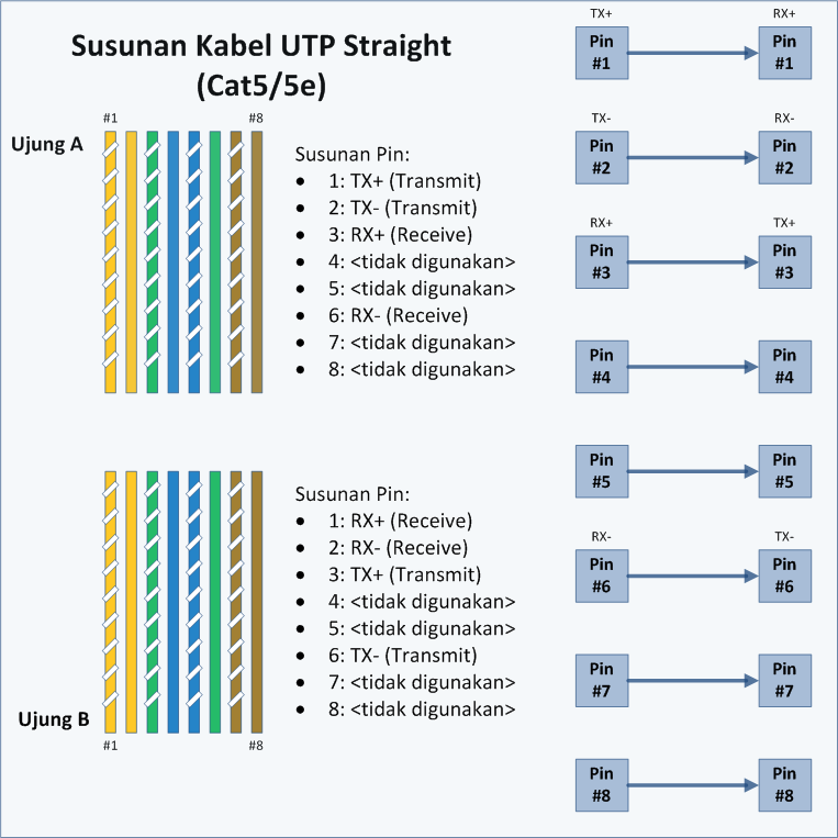


Straight Cable


Straight cable is a term for a cable that uses the same standards on both ends of its wires, could EIA / TIA 568A or EIA / TIA 568B on both ends of the cable. Simply put, the sequence of colors on both ends of the same. In straight cables, pin 1 at one end of the cable connected to pin 1 on the other end, pin 2 connected to pin 2 at the other end, and so on.

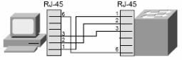
So, when the PC sends data on pin 1 and 2 via the cable straight into the switch, the switch receives data on pins 1 and 2. Well, because pins 1 and 2 on the switch will not be used to send data as well as pins 1 and 2 on the PC, then switch
using pins 3 and 6 to send data to a PC, because PC receives data on pin 3 and 6.

More details, see the following picture:


The use of straight cables:

connect the computer to normal port on the switch.
computer connects to the LAN port cable modem / DSL.
WAN port connects the router to the modem LAN port cable / DSL.
LAN port connects the router to the uplink port on the switch.
connect 2 HUB / switch with one of the HUB / switch uplink port and the other using a common port
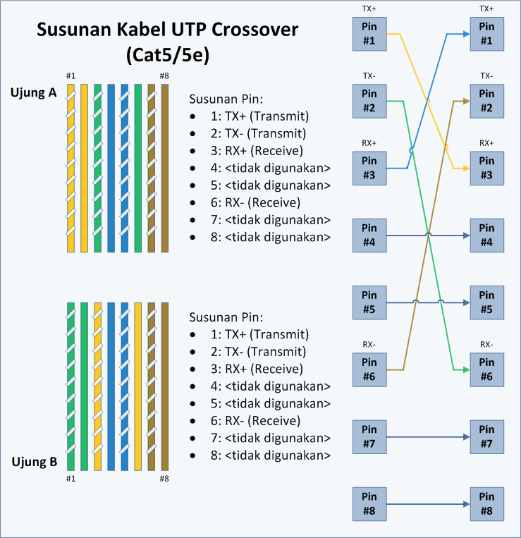
Crossover cable

Crossover cable use the EIA / TIA 568A at one end of the cord and EIA / TIA 568B at the other end of the cable.


In the drawing, pins 1 and 2 at the end A is connected to pins 3 and 6 at the end of B, as well as pins 1 and 2 at the end B is connected to pins 3 and 6 at the end of A. Thus, pins 1 and 2 at each end of the cable used to transmit data, while pins 3 and 6 on each end of the cable used to receive data, because the pins 1 and 2 are connected as opposed to pins 3 and 6.

To identify whether a crossover or straight cable is to only see one end of the cable. If the sequence of colors of the wires on pin 1 is White Green, then the cable is a crossover (although if the other end also has the same color sequence that is White Green as pin 1, then the cable is a Straight). But fortunately, most cables use a standard EIA / TIA 568B on both ends of the cord.

Use a crossover cable:

connect 2 computers directly
connecting 2 pieces HUB / switch using regular port between the two HUB / switch.
connect the computer to switch uplink port
LAN port connects the router to a regular port on the HUB / switch

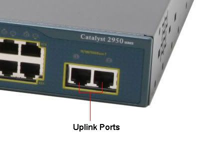
Vs. regular port. uplink ports

To connect the two HUB / switch, or connect two computers directly needed a crossover cable. But if the HUB / switch or Network Interface Card (NIC) or other network equipment to provide Uplinkport or MDI / MDI-X you can use straight cables for connecting to a regular port on the HUB / switch or Network Interface Card or other network equipment.

Here is the order of the cord:


Design by Free WordPress Themes | Bloggerized by Lasantha - Premium Blogger Themes | Lady Gaga , Salman Khan